Computer-Aided Design for Electromechanical Systems in EMET 110 Assignments
.svg)
- CAD Foundations Covered in EMET 110
- Creating Engineering Drawings for Mechanical Components
- Producing CAD Documentation for Electrical Equipment
- Drawing Standards Applied in EMET 110 Assignments
- Dimensioning and Tolerancing in CAD Drawings
- Layer Management, Symbols, and Annotation
- 3D Modeling and Assembly Work in EMET 110
- Building Parametric Parts for Electromechanical Designs
- Assembly Modeling and Interference Checking
- CAD Documentation Expected in EMET 110 Assignments
- Preparing Manufacturing-Ready Drawing Sheets
- Revising and Organizing CAD Files for Assignment Projects
Computer-Aided Design (CAD) is the central focus of EMET 110, where students begin developing the technical drawing and digital modeling skills required for electromechanical engineering technology. The course introduces the use of CAD software to create engineering drawings that accurately represent mechanical parts, assemblies, and equipment used in electromechanical applications. Through lectures and laboratory exercises, students learn how digital drafting replaces traditional manual drawing methods while improving precision, consistency, and documentation quality. Because these projects demand a high level of drafting accuracy and adherence to engineering standards, many students seek AutoCAD Assignment help to better understand drawing requirements, CAD workflows, and technical documentation practices. EMET 110 assignments require students to apply these CAD techniques to projects that emphasize engineering standards, drawing accuracy, and clear graphical communication. Instead of simply producing digital sketches, students prepare engineering documentation that reflects the requirements of real electromechanical design projects, making the course an essential foundation for subsequent technical subjects within the Electro-Mechanical Engineering Technology program.
CAD Foundations Covered in EMET 110
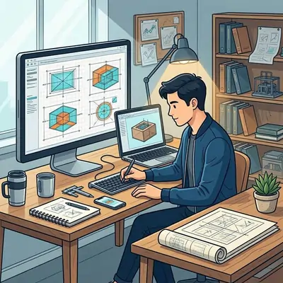
EMET 110 introduces students to the fundamental principles of computer-aided design before they begin producing complete engineering drawing packages. Assignments gradually progress from creating individual components to preparing more detailed technical documentation for electromechanical systems. Throughout the course, students become familiar with CAD tools used to generate precise geometry, organize drawing information, and communicate engineering ideas visually. Laboratory activities reinforce classroom instruction by allowing students to practice drafting techniques using professional software while following accepted engineering drawing standards. Every assignment strengthens the ability to convert engineering ideas into technical drawings that can be interpreted accurately by engineers, technicians, and manufacturing personnel.
Creating Engineering Drawings for Mechanical Components
One of the primary objectives of EMET 110 assignments is developing accurate engineering drawings for mechanical components used within electromechanical systems. Students begin by creating standard drawing views, including front, top, side, sectional, and auxiliary views that completely describe a component's geometry. These drawings must accurately represent shape, size, and design features while following engineering drafting conventions taught throughout the course.
As assignments become more detailed, students learn how proper line types, projection methods, and view arrangements improve the readability of engineering drawings. Hidden lines identify internal features, centerlines define symmetrical geometry, and sectional views reveal interior details that cannot be shown clearly using external views alone. Understanding when and how each drawing technique should be applied enables students to produce documentation suitable for engineering analysis and manufacturing interpretation.
Dimension placement is another important requirement within EMET 110 assignments. Students learn that dimensions should completely define a part without unnecessary duplication while maintaining logical organization across the drawing sheet. Clear dimensions reduce manufacturing uncertainty and allow every feature of a component to be reproduced accurately. The course places considerable emphasis on presenting dimensions that remain easy to interpret, even when drawings become increasingly complex.
Assignments also introduce title blocks, drawing scales, sheet organization, and drawing layouts that support professional engineering documentation. Students are expected to submit drawings that not only contain accurate geometry but also follow consistent formatting practices. These requirements demonstrate that computer-aided design involves much more than operating CAD software; it requires producing engineering documents capable of communicating technical information effectively.
Producing CAD Documentation for Electrical Equipment
EMET 110 extends beyond purely mechanical drafting by introducing documentation methods that support electrical equipment incorporated within electromechanical systems. Assignments require students to consider how electrical devices are physically arranged within mechanical structures while maintaining accurate engineering representation throughout the drawing package.
Students prepare layouts showing equipment locations, mounting arrangements, enclosure positions, and associated hardware that support electrical installations. These drawings emphasize the physical integration of electrical components rather than electrical circuit analysis, allowing students to understand how CAD documentation contributes to equipment installation and maintenance activities.
Assignments frequently require consistent placement of electrical equipment across multiple drawing views. Students learn that changes made within one drawing often affect associated layouts, requiring careful coordination throughout the entire documentation package. Maintaining consistency between individual component drawings and larger assembly layouts develops attention to detail that becomes increasingly valuable during more advanced engineering technology coursework.
Laboratory exercises also introduce students to drawing organization techniques that separate mechanical features, electrical hardware, dimensions, and annotations into structured CAD files. Organizing drawings systematically improves readability while simplifying future revisions. By developing these documentation practices early in the curriculum, EMET 110 establishes drafting habits that support increasingly sophisticated electromechanical design projects.
Drawing Standards Applied in EMET 110 Assignments
Professional engineering drawings follow recognized drafting standards that ensure technical information is communicated consistently regardless of who prepares the documentation. EMET 110 emphasizes these standards throughout every assignment, requiring students to produce drawings that meet accepted engineering practices rather than simply generating visually correct models. The course teaches that standardized documentation improves communication among designers, manufacturers, technicians, and engineers working on the same electromechanical project. Laboratory assignments reinforce these expectations by evaluating not only the completed drawing but also the organization, formatting, and technical presentation of every engineering document.
Dimensioning and Tolerancing in CAD Drawings
Dimensioning forms one of the most carefully evaluated skills throughout EMET 110 because accurate measurements define every physical characteristic of a manufactured component. Students learn how dimensions should fully describe the geometry of a part while avoiding repeated or conflicting information. Every assignment reinforces logical dimension placement so that manufacturing personnel can interpret the drawing efficiently without relying on assumptions or additional calculations.
The course also introduces tolerance principles that explain acceptable manufacturing variation for selected dimensions. Although EMET 110 focuses primarily on CAD documentation, students begin recognizing that engineering drawings communicate more than nominal measurements. Appropriate tolerances provide guidance regarding allowable variation while maintaining component functionality within an electromechanical assembly.
Assignments require careful placement of extension lines, leader notes, arrows, and dimension text to maintain drawing clarity. Students discover that poorly positioned dimensions may reduce drawing readability even when numerical values are technically correct. Through repeated drafting exercises, they develop consistent documentation habits that improve the overall quality of engineering drawings produced during the course.
Dimensioning assignments often involve updating existing drawings after design modifications. These revision activities reinforce the relationship between part geometry and associated dimensions, encouraging students to verify that every drawing remains complete and internally consistent after changes are introduced.
Layer Management, Symbols, and Annotation
Layer management is an important skill developed through EMET 110 laboratory assignments because electromechanical drawings often contain several different categories of information. Students learn to separate visible object lines, hidden features, centerlines, dimensions, annotations, construction geometry, and reference information into organized CAD layers. This structure improves drawing readability and allows specific information to be displayed, modified, or reviewed without affecting the entire drawing.
Assignments also introduce engineering symbols and annotation practices used to identify components, materials, mounting details, and manufacturing notes. Students must apply these annotations consistently so that drawing packages communicate technical information clearly. Proper labeling becomes especially important when multiple parts or assemblies are included within the same project, since unclear annotations can create confusion during manufacturing or installation.
EMET 110 exercises often require students to update existing drawings while preserving the original organization of layers and annotations. These revision activities reinforce the importance of maintaining consistent CAD standards throughout a project. By organizing drawing information systematically, students develop documentation habits that support larger electromechanical design projects encountered later in the program.
3D Modeling and Assembly Work in EMET 110
After establishing drafting fundamentals, EMET 110 introduces three-dimensional modeling techniques that allow students to visualize electromechanical components more effectively. The laboratory portion of the course provides hands-on experience with creating solid models and assembling multiple parts within a digital environment. These assignments help students understand spatial relationships between components and prepare them for more advanced electromechanical design tasks.
Building Parametric Parts for Electromechanical Designs
Students create parametric CAD models by defining sketches, dimensions, and geometric relationships that describe individual electromechanical components. Rather than drawing static shapes, they learn how model features remain connected so that design changes can be made efficiently. When a dimension is modified, related features update automatically, preserving the intended design relationships.
This approach is particularly valuable in EMET 110 assignments because electromechanical components often require precise dimensions and repeatable modifications. Students practice creating holes, slots, mounting features, extrusions, and other common mechanical elements while maintaining accurate geometric constraints. These exercises strengthen both CAD software proficiency and understanding of component design intent.
Parametric modeling assignments also encourage students to think about how a component may be revised during the design process. Instead of rebuilding a model from the beginning, students can adjust dimensions and allow the CAD system to update the part automatically. This workflow reflects professional engineering practice, where design revisions are common throughout product development.
Assembly Modeling and Interference Checking
EMET 110 assignments frequently progress from individual part models to complete digital assemblies. Students combine multiple components within a single CAD environment to evaluate how parts fit together and interact within an electromechanical system. Assembly modeling helps students understand alignment, spacing, mounting relationships, and overall system organization.
One important aspect of assembly work is interference checking. Students examine whether components overlap or occupy the same physical space within the digital model. Detecting these issues before manufacturing or physical assembly improves design accuracy and reduces potential installation problems. This process demonstrates how CAD software can be used as a verification tool rather than only a drawing tool.
Assembly assignments also require students to maintain correct relationships between parts as modifications are made. If one component changes size or position, associated parts may need to update accordingly. Managing these relationships develops careful modeling habits that are essential for producing reliable electromechanical assemblies.
CAD Documentation Expected in EMET 110 Assignments
The final stage of many EMET 110 projects involves converting CAD models and assemblies into complete engineering documentation. Students are expected to produce drawing packages that contain all information necessary to describe a component or assembly accurately. This includes drawing views, dimensions, annotations, title blocks, revision information, and organized sheet layouts.
Preparing Manufacturing-Ready Drawing Sheets
EMET 110 assignments require students to create drawing sheets that communicate manufacturing information clearly. After completing a CAD model, students generate appropriate drawing views, select suitable scales, and arrange the information logically on the sheet. The objective is to produce documentation that can be interpreted without ambiguity.
Students also add dimensions, notes, and identification information that describe the part or assembly completely. In assembly projects, drawing sheets may include component references, mounting details, and additional views that clarify how parts connect together. These requirements reinforce the idea that engineering documentation must support practical manufacturing and assembly processes.
Attention to sheet organization is emphasized throughout the course. Crowded layouts, inconsistent formatting, or missing information can reduce the effectiveness of an otherwise accurate drawing. By preparing manufacturing-ready drawing sheets, students develop professional documentation skills that extend beyond basic CAD operation.
Revising and Organizing CAD Files for Assignment Projects
Revision management is an important part of EMET 110 because engineering drawings often change during project development. Assignments may require students to modify existing models, update dimensions, adjust annotations, and revise associated drawing sheets while maintaining consistency throughout the documentation package.
Students learn to organize CAD files using logical naming conventions, folder structures, templates, and drawing references. Proper organization reduces the likelihood of using incorrect file versions and makes it easier to locate related project documents. These practices become increasingly important as assignments involve multiple parts and drawing sheets.
By the end of EMET 110, students are expected to produce organized CAD documentation that reflects professional engineering drafting standards. The combination of accurate modeling, clear drawing presentation, assembly verification, and structured file management forms the foundation for later electromechanical engineering technology coursework.