Core Engineering Graphics Skills Developed Through ENGR 130 Assignments
.webp)
- AutoCAD Drafting Skills Practiced in ENGR 130 Assignments
- Creating Accurate Two-Dimensional Engineering Drawings
- Applying Engineering Drawing Standards
- Three-Dimensional Modeling Skills Using SolidWorks
- Developing Parametric Part Models
- Producing Engineering Drawing Views from Models
- Electrical Drawing Skills Introduced in ENGR 130
- Reading Standard Electrical Circuit Symbols
- Preparing Basic Electrical Circuit Diagrams
- Engineering Visualization and Technical Communication in ENGR 130
- Improving Spatial Visualization Through Graphics Assignments
- Communicating Engineering Designs with Professional Documentation
ENGR 130 at the University of Missouri–Kansas City introduces students to engineering graphics through a combination of AutoCAD drafting, SolidWorks modeling, and electrical circuit diagram preparation. The course is designed for students with little or no previous CAD experience and gradually develops the technical drawing skills required in mechanical, electrical, and computer engineering programs. Students who are building these foundational drafting abilities often seek AutoCAD Assignment help to better understand engineering drawing standards, drawing layouts, and the accurate use of CAD tools in their coursework.
Rather than concentrating only on software commands, ENGR 130 assignments emphasize the communication of engineering ideas through standardized drawings, three-dimensional models, and electrical schematics. As students progress through the course, they prepare professional engineering documentation while strengthening their visualization and technical drafting skills. Many students also require assistance with Electrical Layouts assignment to improve their understanding of circuit diagrams, electrical drawing conventions, and the organized presentation of engineering information alongside mechanical graphics.
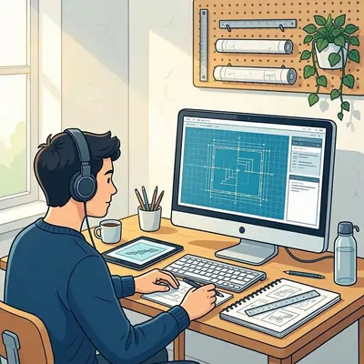
AutoCAD Drafting Skills Practiced in ENGR 130 Assignments
The first section of ENGR 130 assignments focuses on building a strong foundation in two-dimensional drafting using AutoCAD. Every exercise is designed to improve drawing precision while introducing engineering documentation standards that students will continue using in advanced engineering courses. Instead of producing simple sketches, students prepare technical drawings that accurately represent engineering components using dimensions, annotations, and organized layouts. These assignments gradually increase in complexity so that students understand both drafting techniques and the importance of technical communication.
Creating Accurate Two-Dimensional Engineering Drawings
One of the primary objectives of ENGR 130 is teaching students how to produce accurate engineering drawings in AutoCAD. Early assignments introduce drawing tools for creating lines, circles, arcs, polygons, and other geometric entities before progressing to more detailed engineering objects. Students learn how coordinate systems, object snaps, and precision drawing commands contribute to producing technically correct drawings rather than approximate sketches.
As assignments become more detailed, students apply editing tools such as trimming, extending, offsetting, mirroring, rotating, and copying to refine engineering geometry efficiently. They also learn how to organize drawings using layers so different engineering features remain clearly separated throughout the drafting process. These exercises demonstrate that engineering graphics depend on both drafting accuracy and organized documentation. Students who require additional support while completing these technical drawing exercises often look for AutoCAD assignment help to strengthen their understanding of drafting workflows and engineering drawing requirements.
Applying Engineering Drawing Standards
Creating geometry represents only one part of ENGR 130 coursework. Every assignment also requires students to apply engineering drawing standards that allow technical information to be interpreted consistently by other engineers. Proper documentation is treated as an essential part of every drawing rather than an optional finishing step.
Students prepare title blocks that identify drawing information, apply dimensions according to engineering drafting conventions, and place annotations where they improve drawing readability without creating unnecessary clutter. They also learn the purpose of centerlines, hidden lines, construction lines, and different line weights used throughout engineering graphics. Assignments evaluate whether dimensions are complete, properly positioned, and logically organized so that another engineer could manufacture or inspect the represented component without confusion.
This emphasis on documentation helps students recognize that engineering graphics serve as a universal technical language. By following accepted drafting standards throughout ENGR 130 assignments, students develop documentation habits that remain valuable in later design, manufacturing, and engineering analysis courses.
Three-Dimensional Modeling Skills Using SolidWorks
Once students establish confidence with two-dimensional drafting, ENGR 130 expands into three-dimensional modeling using SolidWorks. The transition from AutoCAD drawings to digital models demonstrates how engineering components are represented throughout modern product development. Assignments encourage students to understand the relationship between sketches, features, and complete engineering models while maintaining dimensional accuracy established during the drafting stage.
Developing Parametric Part Models
SolidWorks assignments introduce students to feature-based modeling, where engineering components are created from sketches that define the overall design. Students begin by preparing fully constrained sketches before converting them into solid models using extrusion, revolution, and additional modeling operations. Every feature is connected to previous design decisions, allowing the entire model to update automatically whenever dimensions or sketch geometry change.
As students complete additional assignments, they incorporate engineering features such as fillets, chamfers, holes, and cut operations that resemble actual manufactured parts. Instead of treating each model as an isolated project, ENGR 130 emphasizes the importance of planning sketches carefully because later modifications depend on the original design intent. This workflow introduces students to the parametric modeling approach widely used across engineering industries for product design and manufacturing.
Assignments also reinforce dimensional consistency by requiring students to verify model accuracy throughout the modeling process. Small changes in measurements affect the entire component, helping students appreciate the importance of precision when developing engineering designs digitally.
Producing Engineering Drawing Views from Models
ENGR 130 assignments extend beyond creating three-dimensional models by requiring students to generate complete engineering drawings directly from SolidWorks components. This stage demonstrates how digital models and traditional engineering documentation work together throughout engineering practice.
Students prepare orthographic projections that display the front, top, and side views of components while maintaining accurate dimensions across every drawing. They also generate isometric views that improve visualization and section views that reveal internal features hidden within the solid model. These assignments strengthen spatial reasoning because students must understand how one physical object appears from multiple viewing directions while preserving dimensional relationships.
The process of converting three-dimensional models into engineering drawings also reinforces the connection between AutoCAD drafting principles and SolidWorks modeling techniques introduced earlier in ENGR 130. Rather than treating the two software packages separately, the course demonstrates how engineering graphics integrate drafting, modeling, and documentation into one coordinated design process. Students therefore finish this portion of the course with stronger visualization abilities and a clearer understanding of how engineering drawings accurately communicate complete product designs.
Electrical Drawing Skills Introduced in ENGR 130
In addition to mechanical drafting and three-dimensional modeling, ENGR 130 introduces students to the preparation and interpretation of electrical circuit diagrams. This component broadens the scope of engineering graphics by demonstrating that standardized graphical communication is equally important in electrical engineering. Instead of focusing on circuit analysis or advanced electrical calculations, the assignments emphasize how electrical information is represented accurately through engineering drawings. Students learn that consistent symbols, organized layouts, and proper documentation are essential for creating schematics that can be understood by engineers, technicians, and manufacturers.
Reading Standard Electrical Circuit Symbols
One of the first electrical graphics skills developed in ENGR 130 assignments is the ability to recognize and interpret standardized circuit symbols. Students study commonly used symbols representing resistors, switches, voltage sources, grounds, conductors, connectors, lamps, and other basic electrical components. These symbols replace detailed illustrations of actual devices, allowing engineers to communicate circuit designs efficiently using internationally recognized drafting conventions.
Assignments often require students to identify individual components within existing schematics before interpreting how those components are connected. Rather than memorizing symbols in isolation, students analyze complete circuit diagrams to understand the relationships between different electrical elements. This process develops the ability to read engineering documentation accurately, which becomes increasingly important in later electrical engineering courses involving more advanced circuit design.
Students also learn that electrical schematics prioritize logical relationships instead of physical appearance. Components are arranged to improve readability rather than to match their real-world locations, helping students understand the purpose of engineering graphics as a communication tool. By interpreting standardized electrical symbols correctly, students establish a strong foundation for preparing professional engineering documentation throughout the remainder of the course.
Preparing Basic Electrical Circuit Diagrams
After becoming familiar with circuit symbols, students begin creating their own electrical schematics using accepted engineering drawing practices. ENGR 130 assignments require circuits to be organized logically so that electrical connections remain easy to follow without unnecessary crossing conductors or inconsistent symbol placement.
Students apply proper labeling techniques, maintain uniform spacing between components, and arrange circuit elements according to drafting standards. The assignments also reinforce the importance of consistency, as symbols, line styles, and annotations must remain clear throughout every drawing. Even relatively simple electrical circuits require careful planning to ensure the completed schematic communicates technical information without ambiguity.
Unlike assignments that emphasize electrical calculations, ENGR 130 evaluates how effectively students prepare engineering documentation that follows graphical conventions. These exercises demonstrate that electrical drawings share many principles with mechanical drawings, including accuracy, readability, organization, and compliance with standardized drafting methods. By combining electrical schematics with AutoCAD drafting experience, students develop engineering graphics skills that apply across multiple engineering disciplines.
Engineering Visualization and Technical Communication in ENGR 130
Throughout ENGR 130, engineering visualization and technical communication are developed alongside software proficiency. Every assignment encourages students to think beyond drawing creation by understanding how engineering information is interpreted by others. Whether preparing AutoCAD drawings, SolidWorks models, or electrical circuit diagrams, students are expected to communicate technical details clearly using accepted engineering graphics standards. This combination of visualization and documentation forms one of the most important outcomes of the course.
Improving Spatial Visualization Through Graphics Assignments
Spatial visualization is strengthened continuously as students work with multiple forms of engineering representation. Early AutoCAD assignments require students to interpret dimensions and geometric relationships accurately, while later SolidWorks exercises challenge them to convert two-dimensional sketches into complete three-dimensional models. This progression helps students mentally visualize engineering components before constructing them digitally.
Assignments involving orthographic projections further develop visualization skills by requiring students to identify how different views represent the same object. Students compare front, top, side, isometric, and section views to understand the complete geometry of engineering parts. They also learn to recognize hidden features that cannot be observed directly in every drawing view, improving their ability to interpret complex engineering documentation.
Visualization exercises extend to electrical graphics as well, where students analyze circuit layouts to understand how individual components function together within a complete schematic. Although electrical diagrams differ from mechanical drawings, both require students to interpret standardized graphical information accurately. This consistent emphasis on visualization prepares students for advanced engineering courses that depend heavily on engineering graphics and digital design.
Communicating Engineering Designs with Professional Documentation
The final collection of ENGR 130 assignments integrates drafting accuracy, three-dimensional modeling, and electrical schematic preparation into complete engineering documentation. Students produce engineering drawings that include dimensions, annotations, title blocks, drawing views, and standardized graphical conventions while ensuring every element contributes to clear technical communication.
Assignments require careful attention to documentation quality because engineering drawings often serve as references for manufacturing, inspection, assembly, and future design modifications. Students therefore learn that incomplete dimensions, inconsistent symbols, or poorly organized layouts can reduce the effectiveness of an otherwise accurate design. This reinforces the importance of preparing engineering graphics that communicate information precisely rather than relying on verbal explanations.
ENGR 130 also demonstrates how multiple engineering graphics tools complement one another throughout the design process. AutoCAD supports precise two-dimensional drafting, SolidWorks provides detailed three-dimensional modeling, and electrical schematic preparation introduces another form of standardized engineering communication. By working across these graphical formats, students gain experience producing engineering documentation that reflects professional practice across mechanical and electrical engineering applications.
As students complete the sequence of ENGR 130 assignments, they develop a comprehensive understanding of engineering graphics that extends beyond software operation. The course establishes the technical drawing, visualization, modeling, and documentation skills required for later engineering coursework while illustrating how engineering graphics support accurate communication across multiple engineering disciplines. This combination of drafting standards, digital modeling, and electrical drawing preparation makes ENGR 130 an important foundation for students beginning their engineering education.